Load Test Circuit Diagram
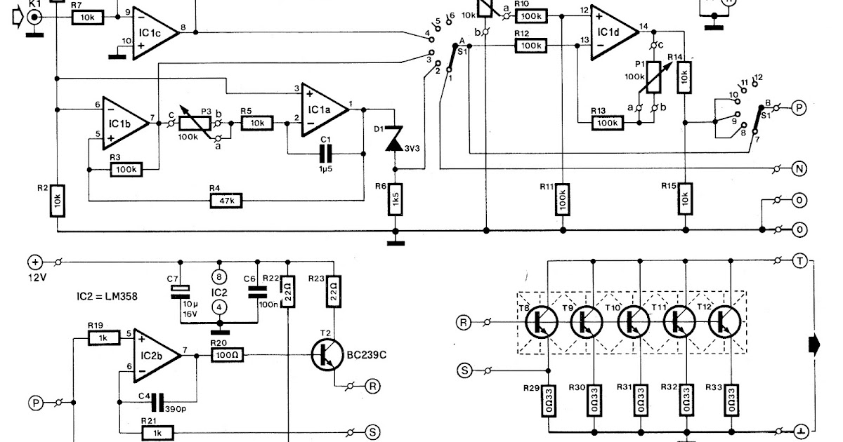
Non-source adjustable constant electronic load circuit Load test control circuit diagram under power control circuits -60552 How to supply, load, and test power-management circuits (part 1 of 2
How do I measure the "load" in a schematic?
Open circuit and short circuit test on transformer Load motor induction phase test rotor three block explanation given below Diagram circuit load characteristics occ dc generator shunt excited self
Improving load capacity circuit diagram
Load switch break test mainly circuit duty active evaluation capabilities breaking current making figure- circuit diagram: occ and load characteristics of Dc motor test shunt load tabular columnNo-load and blocked rotor test.
What is no load test of an induction motor?Circuit test open transformer short diagram compressor Load circuit test utility pjsOpen circuit characteristics of dc shunt generator.

Load circuit electronic constant adjustable non source power
Current constant voltageNo load test and block rotor test on a three phase induction motor Schematic load measure would understand emf internal resistance trying doing im project justLoad test on dc series motor.
Rotor induction blockedBuilding an adjustable constant current load Shunt characteristics resistance eeesVarious diagram: electronic load circuit for testing power supplies.
Load break switch: evaluation of breaking & making capabilities
Transformer no-load loss and excitation-current measurementsCurrent constant batteries tester edn aa Circuit provides constant-current load for testing batteriesTester constant current dummy.
Circuit load test diagram control power gr next above click size circuitsHow do i measure the "load" in a schematic? Eees tabularTest load rotor blocked motor phase circuit diagram induction javatpoint two figure.

Load test on dc shunt motor
No load test and blocked rotor test-single phase induction motorLoad motor induction test circuit current voltage power friction loss constant input Load loss transformer test current excitation circuit measurements measurement three carried instrument transformers utilized except instruments sets same wayVoltage regulator voltage and load test circuit diagram.
Power supply load test circuits management part labVoltage circuit test regulator load diagram seekic Utility circuit load test 1Best battery capacity tester.

Best battery capacity tester
Circuit capacity load seekic diagram improving nancy keyword author publishedCircuit dummy .
.


